Mackie CR1604 Owner's Manual
Browse online or download Owner's Manual for Audio mixers Mackie CR1604. Mackie CR1604 Owner`s manual User Manual
- Page / 51
- Table of contents
- BOOKMARKS
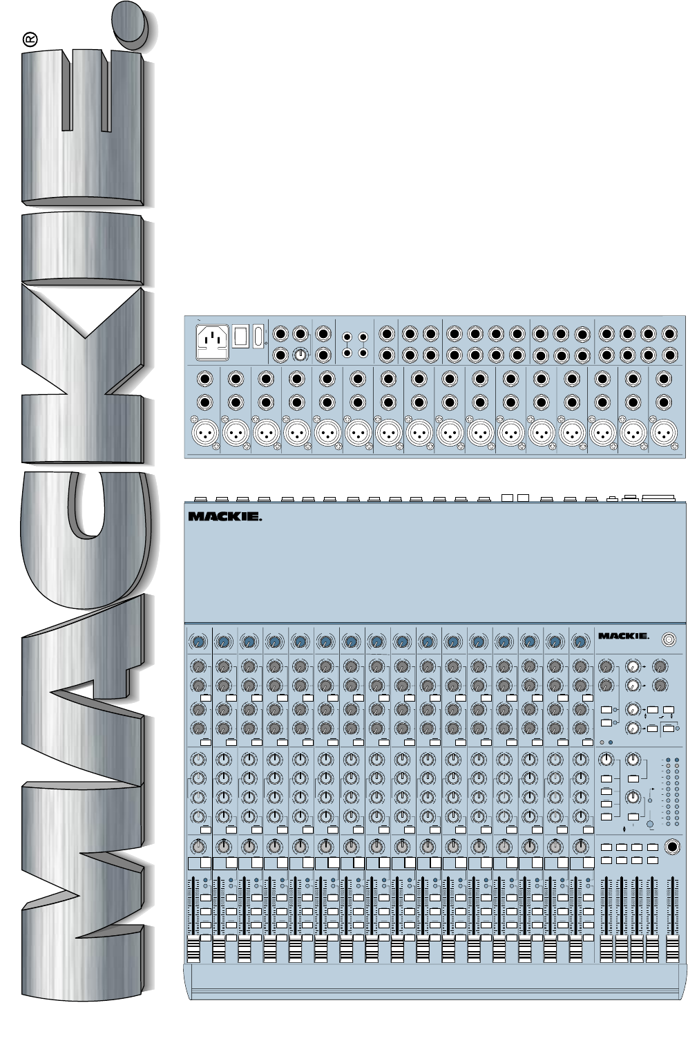
- CR1604-VLZ 1
- LINE MIXER 1
- OWNER’S MANUAL 1
- SAFETY INSTRUCTIONS 2
- READ THIS PAGE!!! 3
- INTRODUCTION 4
- CONTENTS 5
- HOOKUP DIAGRAMS 6
- CR1604-VLZ Stereo P.A 7
- CR1604-VLZ Video Setup 8
- CONVERTING TO RACKMOUNT MODE 9
- PATCHBAY DESCRIPTION 10
- LINE INPUTS 11
- DIRECT OUT 11
- SPLIT MONITORING 12
- AUX SEND OUTPUTS 12
- Double Busing 13
- PHONES OUTPUT 14
- TAPE OUTPUT 14
- TAPE INPUT 14
- TIPSLEEVE 15
- POWER SWITCH 16
- POWER LED 16
- PHANTOM SWITCH 16
- PHANTOM LED 16
- BNC LAMP SOCKET 16
- CHANNEL STRIP DESCRIPTION 17
- –20 (SOLO) LED 18
- OL (MUTE) LED 18
- CONSTANT LOUDNESS ! ! ! 19
- 3-BAND MID-SWEEP EQ 19
- Stereo Sources 19
- LOW CUT 20
- AUX 1, 2, 3, & 4 20
- 5/6 SHIFT 21
- OUTPUT SECTION DESCRIPTION 22
- C-R/PHONES 23
- TAPE IN (LEVEL) 23
- TAPE TO MAIN MIX 23
- LEVEL SET LED 24
- SOLO (LEVEL) 24
- RUDE SOLO LIGHT 24
- Meters vs. Reality 25
- AUX TALK 25
- AUX SENDS (MASTER) 25
- AUX SENDS SOLO 26
- AUX RETURNS (LEVEL) 26
- EFFECTS TO MONITORS 26
- MAIN MIX TO SUBS (AUX RET 3) 26
- 1–2/3–4 (AUX RET 3) 26
- C-R/PHNS ONLY (AUX RET 4) 27
- RETURNS SOLO 27
- MODIFICATIONS 28
- CR1604-VLZ Source Mod 29
- CR1604-VLZ BLOCK DIAGRAM 30
- GAIN STRUCTURE DIAGRAM 31
- SPECIFICATIONS 32
- SERVICE INFO 33
- APPENDIX A: GLOSSARY 34
- APPENDIX B: CONNECTIONS 42
- SPECIAL MACKIE CONNECTIONS 43
- SWITCHED 43
- ⁄4" PHONE JACKS 43
- RCA PLUGS AND JACKS 43
- UNBALANCING A LINE 43
- TRS Send/Receive Insert Jacks 44
- Mono, Stereo, Whatever 44
- MULTS AND “Y”s 45
- APPENDIX C: BALANCED LINES 46
- PHANTOM POWERING, GROUNDING 46
- AND OTHER ARCANE MYSTERIES 46
- DO DON’T 47
- Grounding 48
- FREE T-SHIRT OFFER 49
- Session: 50
- CHANNEL MIC/LINE MIXER 51
Summary of Contents
CR1604-VLZMIC/LINE MIXEROWNER’S MANUALAUXSENDSSTEREO AUX RETURNSEFFECTS TOMONITORSTO AUXSEND 2TO AUXSEND 112PWRPHANSOLOSOLO12123412C-R / PHNSONLYRETUR
10At the risk of stating the obvious, this iswhere you plug everything in: microphones,line-level instruments and effects, and the ulti-mate destinati
11 LINE INPUTSThese 1/4" jacks share circuitry (but notphantom power) with the mic preamps. Youcan use these inputs for virtually any signalyou’l
12 SPLIT MONITORINGWith split monitoring, you use the first eightchannels for your sound sources: vocal mics,drum mics, keyboard/synth outputs, guitar
13 EFFECTS: SERIAL OR PARALLEL?You’ve heard us carelessly toss around theterms “serial” and “parallel.” Here’s what wemean by them:“Serial” means that
14This method is exactlythe same as the double-busing feature found inother mixers. Built-in doublebusing is nothing more thanY-cords living inside th
15 MAIN INSERTThese 1/4" jacks are for connecting serialeffects such as compressors, equalizers, de-essers, or filters . The INSERT point is afte
16 POWER SWITCHIf this one isn’t self-explanatory, we give up.You can leave this switch on all the time; theCR1604-VLZ is conservatively designed, so
17 CHANNEL STRIP DESCRIPTIONA Clean FadeFaders are not rocketscience — they operate bydragging a metal pin (thewiper) across a carbon-basedstrip (the
18If you’re printing new tracks or bouncing ex-isting ones, you’ll also use the 1–2 and 3–4switches, but not the L–R switch. Here, youdon’t want the s
19CONSTANT LOUDNESS ! ! !The CR1604-VLZ’s PANcontrols employ a designcalled “Constant Loudness.”It has nothing to do withliving next to a freeway. As
CAUTION AVISRISK OF ELECTRIC SHOCK DO NOT OPENRISQUE DE CHOC ELECTRIQUENE PAS OUVRIRCAUTION: TO REDUCE THE RISK OF ELECTRIC SHOCKDO NOT REMOVE COVE
2020Hz 100Hz 1kHz 10kHz 20kHz–15–10–50+5+10+1520Hz 100Hz 1kHz 10kHz 20kHz–15–10–50+5+10+15Most of the root and lower harmonics thatdefine a sound are
21We recommend going into a stereo reverb inmono and returning in stereo. We have foundthat on most “stereo” reverbs, the second inputjust ties up an
22AUXSENDSSTEREO AUX RETURNSEFFECTS TOMONITORSTO AUXSEND 2TO AUXSEND 112PWRPHANSOLOSOLO12123412C-R / PHNSONLYRETURNSSOLOMAIN MIXTO SUBSASSIGN OPTIONS1
23Now you know how to select the signals youwant to send to the engineer’s control roomand/or phones. From there, these signals all passthrough the sa
24 MODE (NORMAL (AFL)/LEVEL SET (PFL))You may have already seen this, but in caseyou missed it: The CR1604-VLZ’s solo systemcomes in two flavors: NORM
25 METERSThe CR1604-VLZ’s peak metering system ismade up of two columns of twelve LEDs. Decep-tively simple, considering the multitude of signalsthat
26 AUX SENDS SOLOOnce again, in a live sound situations AUXSEND 1 and 2 are likely to feed your stagemonitors. You’ll want to check the mix you’resend
27MIX (MAIN MIX TO SUBS switch up) and youdid a drum fade-out using subgroup faders 1and 2, the “dry” signals would fade out, but the“wet” signals wou
28 MODIFICATIONSCR1604-VLZ Post-EQ ModThis changes AUX SENDS 1 and 2, with thepre switch engaged, to receive their signals post-EQinstead of pre-EQ. T
29UL WarningCAUTION! These modi-fication instructions arefor use by qualified per-sonnel only. To avoidelectric shock, do not perform any servicingoth
3We realize that you must have a powerfulhankerin’ to try out your new CR1604-VLZ.Or you might be one of those people whonever reads manuals. Either w
30 CR1604-VLZ BLOCK DIAGRAMMAIN LSUB 3MAIN RSUB 2SUB 1SUB 4AUX 1AUX 2AUX 3AUX 4AUX 5AUX 6SIP LSIP RPFLLOGIC75HzHPFMID HI80 100–8K 12KLOLR1234SIP LSIP
31 GAIN STRUCTURE DIAGRAM+22dBu max in10dB loss, TRIM down40dB gain, TRIM upLINE IN, all channelsMIC IN, all channels60dB gain, TRIM up10dB gain, TRIM
32 SPECIFICATIONSMain Mix Noise20Hz–20kHz bandwidth, 1⁄4" Main Out, channel Trims @unity gain, channel EQs flat, all channels assigned to MainMix
33 SERVICE INFODetails concerning Warranty Service arespelled out on the Warranty Card includedwith your mixer (if it’s missing, let us knowand we’ll
34This Glossary contains brief definitions ofmany of the audio and electronic terms used indiscussions of sound mixing and recording. Manyof the terms
35consoleA term for a sound mixer, usually a large desk-like mixer.cueingIn broadcast, stage and post-productionwork, to “cue up” a sound source (a re
36echoThe reflection of sound from a surface suchas a wall or a floor. Reverberation and echo areterms that can be used interchangeably, but inaudio p
37second, which gives us the sensation of pitch,harmonics, tone and overtones. Frequency ismeasured in units called Hertz (Hz). One Hertzis one repeti
38input moduleA holdover from the days when the only waythat real consoles were built was in modularfashion, one channel per module. See channelstrip.
39pan, pan potShort for panoramic potentiometer. A panpot is used to position (or even move back andforth) a monaural sound source in a stereomixing f
4AUXSENDSSTEREO AUX RETURNSEFFECTS TOMONITORSTO AUXSEND 2TO AUXSEND 112PWRPHANSOLOSOLO12123412C-R / PHNSONLYRETURNSSOLOMAIN MIXTO SUBSASSIGN OPTIONS1–
40equals the center frequency divided by the dif-ference between the upper and lower –3dBfrequencies. A peaking EQ centered at 10kHzwhose –3dB points
41stereoBelieve it or not, stereo comes from a Greekword that means solid. We use stereo orstereophony to describe the illusion of a con-tinuous, spac
42APPENDIX B: CONNECTIONS“XLR” CONNECTORSMackie mixers use 3-pin female “XLR”connectors on all microphone inputs, withpin 1 wired to the grounded (ear
43goes to the ground (earth) connection atthe unbalanced input. In most cases, thebalanced ground (earth) will also beconnected to the ground (earth)
44input, for example, will automatically unbalancethe input and make all the right connections.Conversely, a 1⁄4" TRS plug inserted into a 1⁄4&qu
45MULTS AND “Y”sA mult or “Y” connector allows you to routeone output to two or more inputs by simplyproviding parallel wiring connections. You canmak
46APPENDIX C: BALANCED LINES,PHANTOM POWERING, GROUNDINGAND OTHER ARCANE MYSTERIESWhat is it, exactly?The obvious external power source for anymodern
47the DC power is applied common-mode. Theaudio travels via pins 2 and 3, the power trav-els between pins 2 and 3 simultaneously, andpin 1 is the grou
48Do’s and Don’ts of Fixed InstallationsIf you install sound systems into fixed installa-tions, there are a number of things that you cando to make yo
49Many “authorities” tell you that shieldsshould only be connected at one end. Some-times this can be true, but for most (99%)audio systems, it is unn
5CONTENTSAUX... 20PRE ... 215/
PANAUX31212121212121212EQ5465/6SHIFTPREPRE PREPRE PRE PRE PRE PRETRIM12345678SOLOL - R3–41–2SOLOL - R3–41–2SOLOL - R3–41–2SOLOL - R3–41–2SOLOL - R3–41
PATENT PENDING4321INSERT INSERT INSERTLINEINSERTMIC 4 MIC 3 MIC 2MIC 1BALUN-BALBALUN-BALBALUN-BALBALUN-BALLINELINELINEOO+6PHANTOMPOWER 120 VAC 50/6
6CR1604-VLZ 8-Track Tracking87654345678910111213141516211234RLRRLRLRLRLR123456DIRECT OUTBAL/UNBALCHANNEL INSERTSAUX RETURNSMAININSERTC/R OUTBAL/UNBALM
7CR1604-VLZ Stereo P.A.8 7654345678910111213141516211234RLRRLRLRLRLR123456CHANNEL INSERTSAUX RETURNSMAININSERTMONOSTEREOPHONESOUT1234CHANNEL INPUTSLLL
8CR1604-VLZ Video Setup8 7654345678910111213141516211234RLRRLRLRLRLR123456CHANNEL INSERTSAUX RETURNSMAININSERTMONOSTEREOPHONESOUT1234CHANNEL INPUTSLLL
9 CONVERTING TO RACKMOUNT MODENot only is the new CR1604-VLZ a compact,professional-quality tabletop mixer, it’s rack-mountable! Its unique rotating i
More documents for Audio mixers Mackie CR1604

Related products and manuals for Audio mixers Mackie CR1604
 (28 pages)
(32 pages)
(6 pages)
(28 pages)
(2 pages)
(19 pages)
(28 pages)
(32 pages)
(6 pages)
(28 pages)
(2 pages)
(19 pages)
 (19 pages)
 (28 pages)
(5 pages)
(110 pages)
(32 pages)
(36 pages)
(32 pages)
(50 pages)
(47 pages)
(28 pages)
(5 pages)
(110 pages)
(32 pages)
(36 pages)
(32 pages)
(50 pages)
(47 pages)
 (18 pages)
© 2020, manymanuals.com. All rights reserved. | 0.921 s |
 Manymanuals.com
 Manymanuals.de
 Manymanuals.fr
 Manymanuals.it
 Manymanuals.pl
 Manymanuals.cz
 Manymanuals.es
 Manymanuals-pt.com
Comments to this Manuals